I gave the step by step in my first post in this thread.
The n/a seal kit doesn't include the necessary o-ring.
The specific o-ring part# is 1 460 210 347.
Andrew
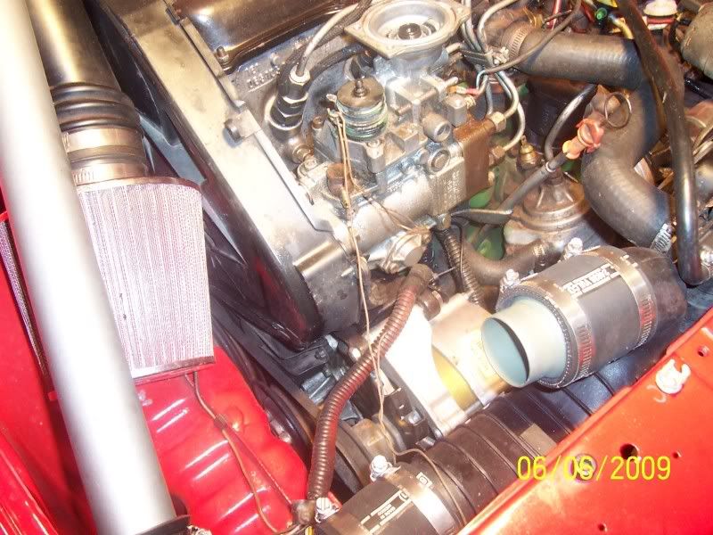
What's this fitting coming from my LDA and why is it blocked
Moderator: Fatmobile
-
Diesel Dean
- Turbo Charger
- Posts: 315
- Joined: Sun Oct 30, 2005 7:12 pm
- Location: Michigan
-
Diesel Dean
- Turbo Charger
- Posts: 315
- Joined: Sun Oct 30, 2005 7:12 pm
- Location: Michigan
I ordered the o ring from a Bosch dealer in Grand Rapids Mich. not to far from here. Thanks for the part number Andrew. They only cost 70 cents so I splurged and bought two. I should have them in a few days. I should say I am terrified to take the top off the pump. Is there anything I should watch for flying springs or gremlins  Just a little woried about messing up the pump. Do you have any pics with the top off Andrew? or the o ring I will be replacing.
Thanks Dean
Thanks Dean
1981 VW Diesel truck / 1984 Rabbit car welded together
-
Diesel Dean
- Turbo Charger
- Posts: 315
- Joined: Sun Oct 30, 2005 7:12 pm
- Location: Michigan
-
timmayjimmay
- Glow Plug
- Posts: 22
- Joined: Thu May 14, 2009 1:35 pm
- Location: Portland, OR
- Contact:
-
Diesel Dean
- Turbo Charger
- Posts: 315
- Joined: Sun Oct 30, 2005 7:12 pm
- Location: Michigan
I haven't had a chance to make a pictorial. I might be able to tomorrow. The hardest part is dealing with the accelerator lever springs and making sure you mark the relationship between the lever and the shaft the nut fastens it to. On the very top of the shaft you'll see a groove. Use a utility blade to scribe a line on the lever inline with that groove. Digital camera pics of the spring setup are a really smart move as well. The rest is fairly simple. For the screws I like to use a screwdriver that accepts bits. Then I use the tightest fitting bit I can find and place a 6 pt 1/4" box wrench around the bit prior to installing it in the screw. I then press firmly down on the handle of the screwdriver to keep the bit seated in place and use the 1/4" wrench to apply awesome torque to the fastener.
Andrew
Andrew
Cleanliness is of utmost importance. Any grit getting into the fuel system can seriously damage the pump or injectors. Clean the exterior of the pump prior to attempting to work on it. A car wash with a pressure washer is one method.
The accelerator lever, max rpm screw and the residual fuel/idle screw all need to be removed in order to access the (4)5mm allen head bolts that hold the pump top to the pump body. They all also need to be returned to their original position on reassembly. To that end, find two extra m6 nuts to use as lock nuts and thread them all the way onto the max rpm screw and the residual fuel/idle screw until they bottom out on the existing lock nut. loosen the existing lock nut slightly and using two wrenches tighten the two lock nuts together on the screw to maintain the position of the original lock nut.

Remove the max rpm and residual fuel/idle screws, label them as to which is which and set them aside.
Use a utility blade to scribe a mark on the throttle levers that aligns with the groove in the top of the accelerator lever shaft.

It's also wise to take a picture of the accelerator lever spring assembly as some are complicated and can be difficult to replace. Having a picture to reference can be helpful. Remove the accelerator lever nut, the lever itself and the return spring(s).
Remove the four (usually) slotted screws that hold the lid on the aneroid.

Those screws can be very tight. I like to use a screwdriver that accepts a bit along with the most tightly fitting bit I can find along with a 6 pt 1/4" wrench (available from craftsman - great investment). I place the bit in the screwdriver and place the wrench around the bit. Then I press firmly down with the screwdriver to keep the bit from slipping out of the screw head while I turn the screw using the wrench. Using the wrench can exert incredible torque.
Once the lid is removed, note or mark how the dimple in the metal diaphragm plate lines up with the aneroid body.

Remove the diaphragm, pin, nylon stop washer and spring and set them aside.
Remove the four allen head bolts that mount the pump lid to the pump body.

In the picture you can see another excellent tool. It accepts typical 1/4" hex bits and yet is a very small ratchet. Another alternative is to use the aforementioned 6pt 1/4" wrench around the body of a bit to loosen those bolts.
When all four bolts are out, press down on the accelerator lever shaft hile lifting up on the lid.

There is a shaft o-ring and so the shaft can be fairly difficult to remove. I would recommend replacing the shaft o-ring on reassembly. Avoid buggering the threads of the shaft or the bushing during removal if any tool is used to push down on the shaft..
With the top off the pump you can see the aneroid lever underneath.

That lever needs to be removed in order to remove the feeler pin in order to replace the offensive o-ring. There is a rod on which the lever pivots. That rod is held in one of two ways. Earlier pumps tend to have a flat head screw on either side of the rod preventing the rod from coming out of the pump. The screws are sealed by copper washers that should be replaced on reassembly. Newer pumps tend to have the rod held in place by a ball bearing pressed in on either side of the rod. If the aneroid has the screws, then using the same technique used on the aneroid lid screws, remove each of the flat head screws that hold the rod in place.

[If the aneroid has the ball bearings, then it is necessary to appropriately support the aneroid and use a punch and hammer to tap on one of the ball bearings until it pushes the rod far enough to push out the opposite ball bearing. Then flip the aneroid over and use the punch on the rod to tap out the remaining ball bearing and the rod itself. The ball bearings can be hammered back into place on reassembly or the holes can be tapped to 1/16 npt and allen head plugs used instead. http://fittingsandadapters.stores.yahoo ... adcou.html]
With the two screws removed, support the aneroid appropriately (I usually place it over the open jaws of my vice) and use a punch and hammer to tap the rod out far enough to remove the lever.

Next, remove the 5mm allen plug that is pictured here:

That plug is also sealed by a copper washer which should be replaced on reassembly.
With the plug removed the feeler pin can now be removed using needle nose pliers. With the feeler pin removed, the o-ring keeper can now be accessed. I've seen two different styles. One was slotted and the other was an allen head style. Use the appropriate bit through the opening to loosen and remove the o-ring keeper.

With the keeper removed the o-ring can now be accessed (woohoo).

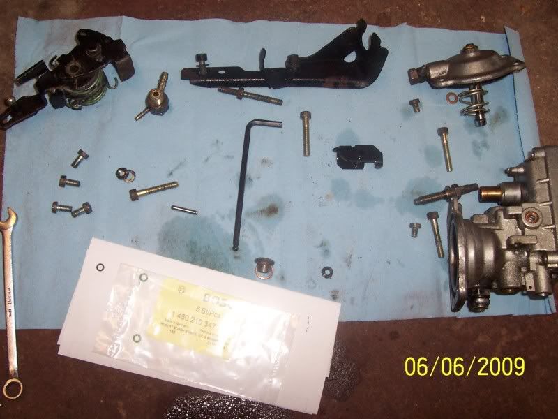
Use a pic or other appropriate tool to remove the o-ring. The new o-ring is usually green. Here they are are side by side.

Lube the new o-ring (I use vaseline) and replace it. Assemble the rest of the aneroid and install it back on the pump.
The accelerator lever, max rpm screw and the residual fuel/idle screw all need to be removed in order to access the (4)5mm allen head bolts that hold the pump top to the pump body. They all also need to be returned to their original position on reassembly. To that end, find two extra m6 nuts to use as lock nuts and thread them all the way onto the max rpm screw and the residual fuel/idle screw until they bottom out on the existing lock nut. loosen the existing lock nut slightly and using two wrenches tighten the two lock nuts together on the screw to maintain the position of the original lock nut.
Remove the max rpm and residual fuel/idle screws, label them as to which is which and set them aside.
Use a utility blade to scribe a mark on the throttle levers that aligns with the groove in the top of the accelerator lever shaft.
It's also wise to take a picture of the accelerator lever spring assembly as some are complicated and can be difficult to replace. Having a picture to reference can be helpful. Remove the accelerator lever nut, the lever itself and the return spring(s).
Remove the four (usually) slotted screws that hold the lid on the aneroid.
Those screws can be very tight. I like to use a screwdriver that accepts a bit along with the most tightly fitting bit I can find along with a 6 pt 1/4" wrench (available from craftsman - great investment). I place the bit in the screwdriver and place the wrench around the bit. Then I press firmly down with the screwdriver to keep the bit from slipping out of the screw head while I turn the screw using the wrench. Using the wrench can exert incredible torque.
Once the lid is removed, note or mark how the dimple in the metal diaphragm plate lines up with the aneroid body.
Remove the diaphragm, pin, nylon stop washer and spring and set them aside.
Remove the four allen head bolts that mount the pump lid to the pump body.
In the picture you can see another excellent tool. It accepts typical 1/4" hex bits and yet is a very small ratchet. Another alternative is to use the aforementioned 6pt 1/4" wrench around the body of a bit to loosen those bolts.
When all four bolts are out, press down on the accelerator lever shaft hile lifting up on the lid.
There is a shaft o-ring and so the shaft can be fairly difficult to remove. I would recommend replacing the shaft o-ring on reassembly. Avoid buggering the threads of the shaft or the bushing during removal if any tool is used to push down on the shaft..
With the top off the pump you can see the aneroid lever underneath.
That lever needs to be removed in order to remove the feeler pin in order to replace the offensive o-ring. There is a rod on which the lever pivots. That rod is held in one of two ways. Earlier pumps tend to have a flat head screw on either side of the rod preventing the rod from coming out of the pump. The screws are sealed by copper washers that should be replaced on reassembly. Newer pumps tend to have the rod held in place by a ball bearing pressed in on either side of the rod. If the aneroid has the screws, then using the same technique used on the aneroid lid screws, remove each of the flat head screws that hold the rod in place.
[If the aneroid has the ball bearings, then it is necessary to appropriately support the aneroid and use a punch and hammer to tap on one of the ball bearings until it pushes the rod far enough to push out the opposite ball bearing. Then flip the aneroid over and use the punch on the rod to tap out the remaining ball bearing and the rod itself. The ball bearings can be hammered back into place on reassembly or the holes can be tapped to 1/16 npt and allen head plugs used instead. http://fittingsandadapters.stores.yahoo ... adcou.html]
With the two screws removed, support the aneroid appropriately (I usually place it over the open jaws of my vice) and use a punch and hammer to tap the rod out far enough to remove the lever.
Next, remove the 5mm allen plug that is pictured here:
That plug is also sealed by a copper washer which should be replaced on reassembly.
With the plug removed the feeler pin can now be removed using needle nose pliers. With the feeler pin removed, the o-ring keeper can now be accessed. I've seen two different styles. One was slotted and the other was an allen head style. Use the appropriate bit through the opening to loosen and remove the o-ring keeper.
With the keeper removed the o-ring can now be accessed (woohoo).
Use a pic or other appropriate tool to remove the o-ring. The new o-ring is usually green. Here they are are side by side.
Lube the new o-ring (I use vaseline) and replace it. Assemble the rest of the aneroid and install it back on the pump.
-
Diesel Dean
- Turbo Charger
- Posts: 315
- Joined: Sun Oct 30, 2005 7:12 pm
- Location: Michigan
Great pictorial Andrew it gave me the confidance to change out the o-ring. The o-ring I took out was old and hard with age. No more leaks now. What do you think about the gov mod. Will it make more power. I have been reading about the mod on vwdiesel.net and have found a few diffrent views on how to do the mod. Where do you add the shims and how many to make the engine rev out.
1981 VW Diesel truck / 1984 Rabbit car welded together
-
Diesel Dean
- Turbo Charger
- Posts: 315
- Joined: Sun Oct 30, 2005 7:12 pm
- Location: Michigan
-
hagar
- Hillbilly Tuner
- Posts: 2424
- Joined: Sat Mar 11, 2006 10:11 am
- Location: Near Lund B.C. Kanada.
LDA Fun.
LDA is a fantastic design by BOSCH and I like the pictorial Bravo Andrew..
Here is a bit of extra information. There are several adjustments possible on the LDA. # 1. : the screw on top (it pushes the "Cone" down) ( to me it is more like a taper pin.) # 2.: a serrated big nut inside Housing it adjusts the spring return tension. (pushes the "Cone" up. # 3 turning the diagfraghm turns the Cone , it is not centered it is like an eccentric pushing guide pin more or less.. # 4. I forgot BUT ask Andrew , his memory is better.
Diesel Dean please go easy on the "POWER" keep cylinder pressure low for a while . I hate to see that beauty destroyed right of the bat. go ECO mode for a while.
hagar.
DD, I'm glad you liked the pictorial and glad it helped. Yes, dealing with the return springs is the only difficult variable, IMO. I haven't dealt with the governor mod very much. If you just want to alter the cutting of fuel by the governor higher in the rpms then if you have any extra available from the accelerator then you can simply turn out the max rpm screw. The result moves the governors effect higher in the rpms, just remember to shift. Otherwise, if you do want to shim the capsule, I'd just shim the main spring.
To add to hagar's post, the adjustments he mentioned are accurate. The spring seat or "star wheel" will adjust the pre-tension on the diaphragm/pin and so will determine boost pressure at which the cone starts moving. The bolt on top sets the original position of the cone. The rotation sets the angle of the taper and so the rate of fueling increase by the LDA.
I wouldn't worry particularly about power hurting anything unless you're pushing more than 20 psi of boost especially considering you are intercooled. Your plastic end-cap intercooler will pop before peak cylinder pressures will hurt your engine. I would have a bit of concern about over-fueling, tho. Keep an eye on the EGTs after any fueling adjustments.
I know you're a fan of ECO mode hagar, but I'm not. Appropriately matching fuel to boost is considerably more efficient than running "super-lean". Any time excess boost is present for the amount of fuel provided means that excess back-pressure is also present and hurting fuel economy. Although with the typical wastegated turbo-charger the issue is moot as the boost pressure will float to equilibrium according to it's efficiency and the current load/fueling. Still, running at full boost with the wastegate regulating boost (and back-pressure) at it's maximum with well-matched fueling will result in better efficiency than running at less than max boost with the wastegate closed and the engine under-fueled. The ECOdiesel was introduced to reduce emissions and be ECOlogical NOT ECOnomical.
Andrew
-
timmayjimmay
- Glow Plug
- Posts: 22
- Joined: Thu May 14, 2009 1:35 pm
- Location: Portland, OR
- Contact:
I just got a boost pressure gauge hooked up and boost looks great whilst driving. I went ahead and did the o-ring fix without instructions and everything is golden. The return springs were actually pretty easy for me. I used a needle nose plier for the bottom spring and vise grips for the top. Since I have TWO turbo diesel Quantums in my driveway I've been able to experiment with LDA and max fuel settings. Before I learned how to tune, I was getting a consistent 36mpg no matter how I drove. With some smart tuning of the fuel screw my last tank got a smidge over 42mpg!! I have turned the max screw out just a hair more and I'm aiming for 50mpg. I have alot of driving this week so I'll keep people posted on here. If my fancy Q doesn't sell on ebay tonight, anyone wanna buy it? I got the vacuum lock system going on it and the power windows/mirrors all work. Beware that turning the max fuel screw out GREATLY decreases power so be prepared for that.