I was directed to the following URL by a helpful injector pump expert:
viewtopic.php?t=5392&highlight=bosch
to see how the Bosch VE injector pump is assembled via a sequence of color photographs. I looked at the photos a couple of weeks ago but they are no longer available on this site. Might someone have an updated URL?
Thanks
Brian
VE injector pump assembly pictures.
Moderator: Fatmobile
-
vaughanatworld
- Glow Plug
- Posts: 3
- Joined: Fri Jun 08, 2007 12:10 pm
Not sure why it disappeared, but here it is again:
Whew...[/quote]
veeman wrote:Ok... I'll do my best. In all honesty, I've never taken a pump apart in this detail , so it might take me a bit to get some of the tech terms for the parts right, but I can always go back and edit those as you guys point them out to me. Just let me know so this thread doesn't get 10 miles long. I've taken a little bit of liberty and tried to clarify some points so the translation is not 100% accurate word by word. Here goes:Then insert the english version of each phrase in turn. Once it's done, I'll make this post a smiley face so that it's not all posted twide. Cheers.
******************
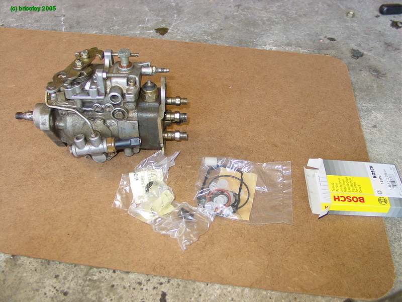
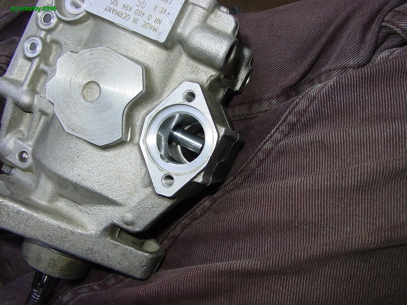
Alright, Folks.... Here’s my Friday night project : prepare a nice working Bosch pump to install on a 205 (Peugeot?).
Since the pump was in unknown condition, it was to be completely taken apart and rebuilt with new gaskets / seals and everything. As it turns out, this was a good move because the inside of it was full of crap..
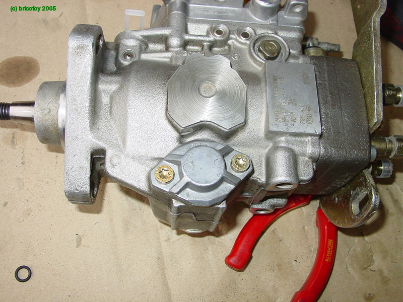
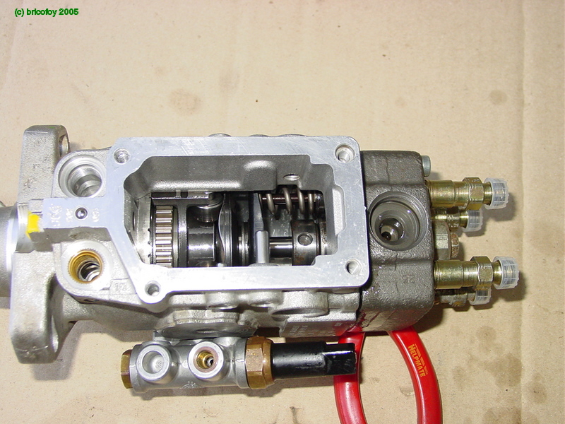
So…Here’s the starting point, the pump and a packet of seals containing the throttle lever sleeve and the mainshaft seal :
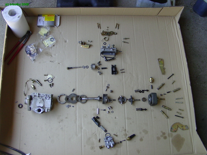
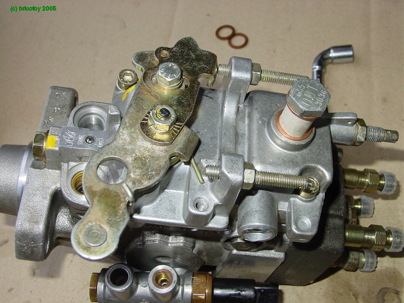
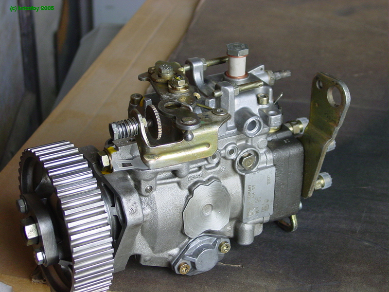
And here's the same thing an hour later..
The Bosch pump looks "crowded" doesn't it?and yet, can't complain, a rotary pump is worse

I didn't take any photos during disassembly, so we'll start from here. If you have any questions about the disassembly, just follow this thread from the bottom up
It goes without saying that once the pump is apart, all the pieces must be rigourously cleaned. In addition, it also greatly helps reassembly to lubricate all parts that adjust, rub or slide together with penetrating oil.
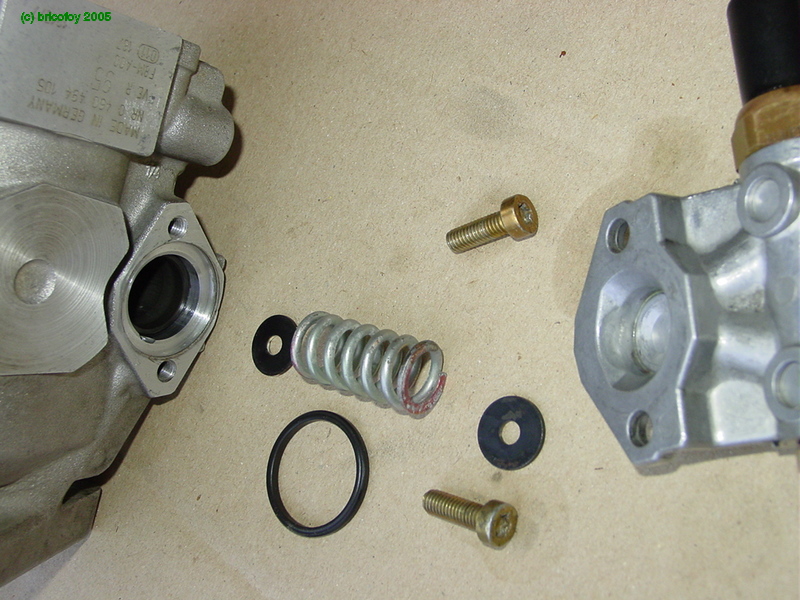
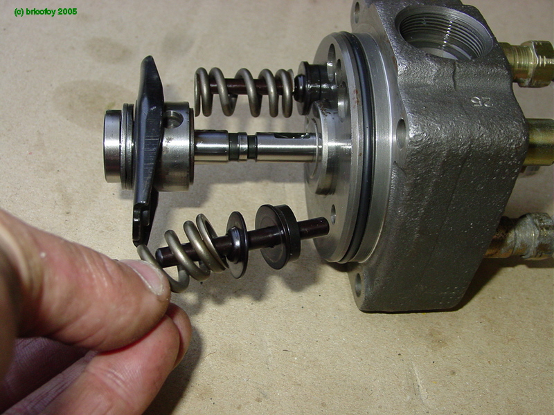
We'll start by reassembling the outlet ports (pressure valves) on the hydraulic head. Here are the different components of the outlet ports: valve, valve spring, adjustment shim, nice new sealing washer and plunger.
The parts reassembled :
and the whole thing :
With that done, let's get on with the "serious" stuff
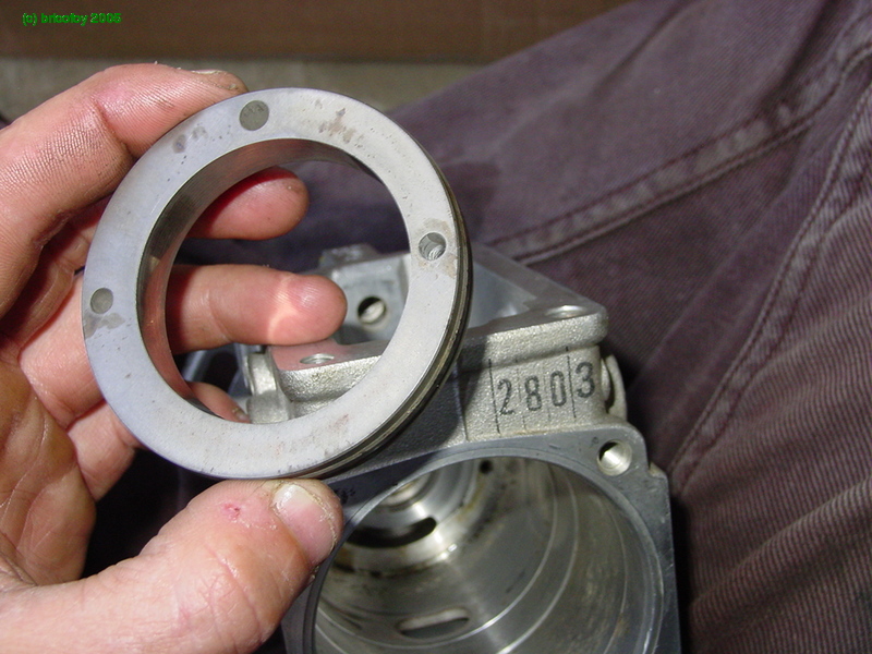
hoooo, it's completely empty ! You can even see my jeans at the bottom of the hole...
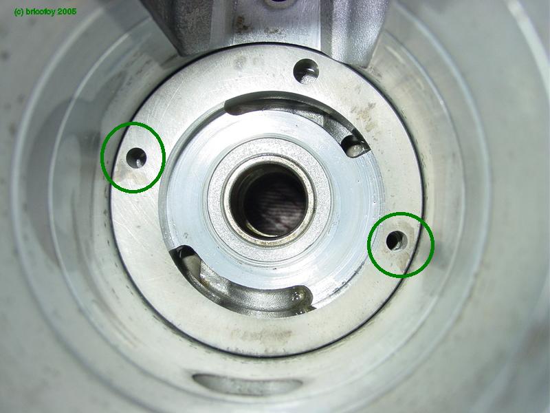
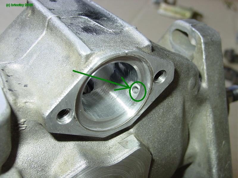
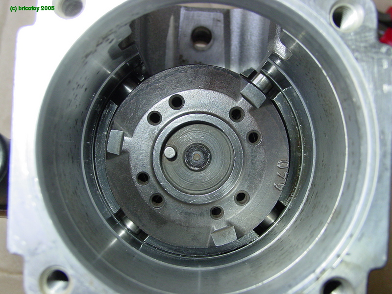
We'll start by reassembling the stator on the transfer pump:
(pay close attention to correctly align the threaded holes with the holes at the bottom of the pump body marked in green)
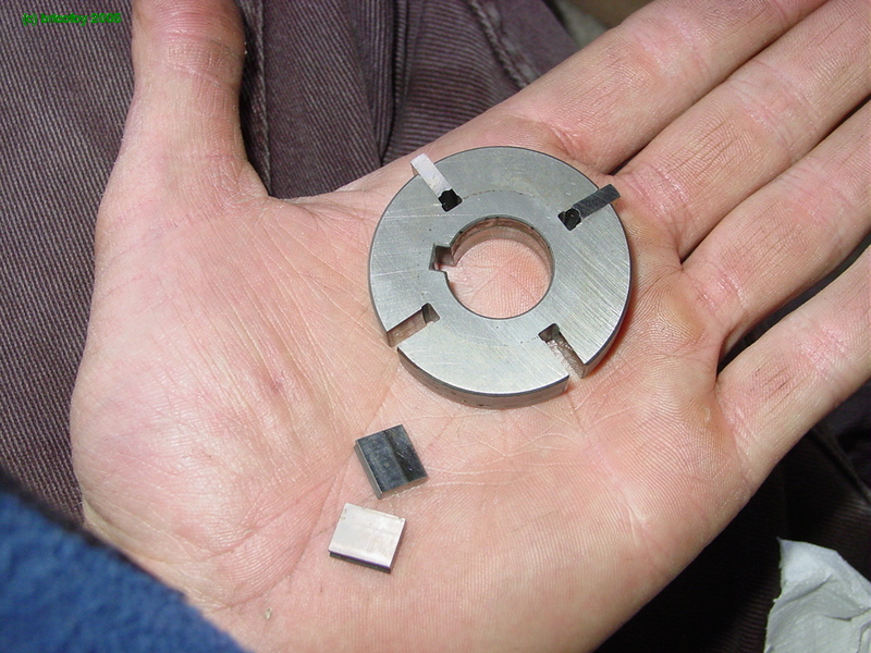
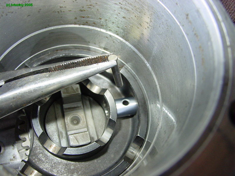
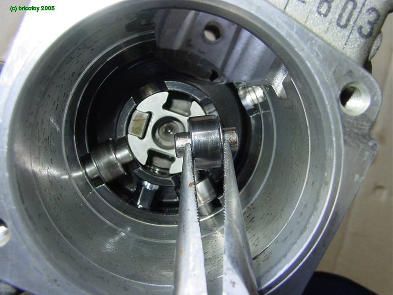
Next, the rotor and its vanes :
First the rotor :
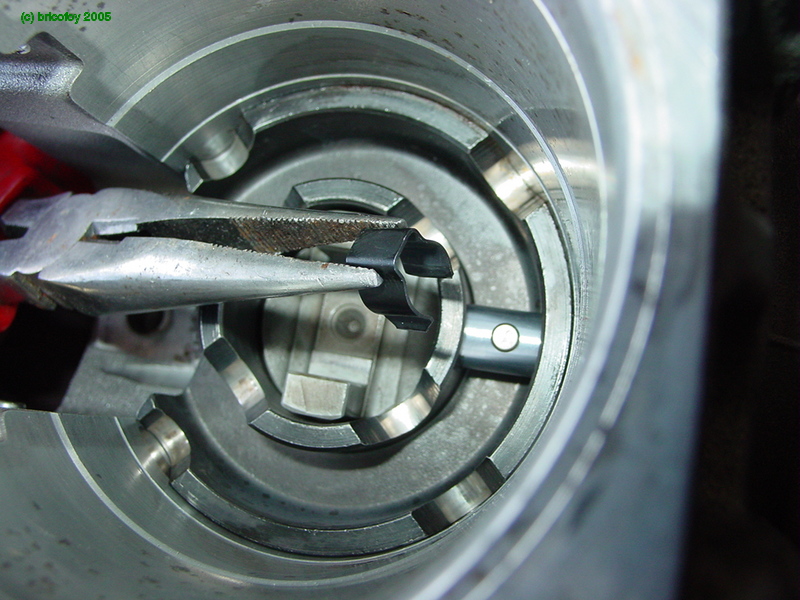
Next the vanes go in with the help of a long needle nose pliers:
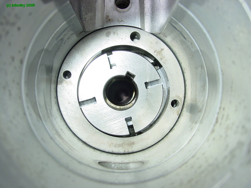
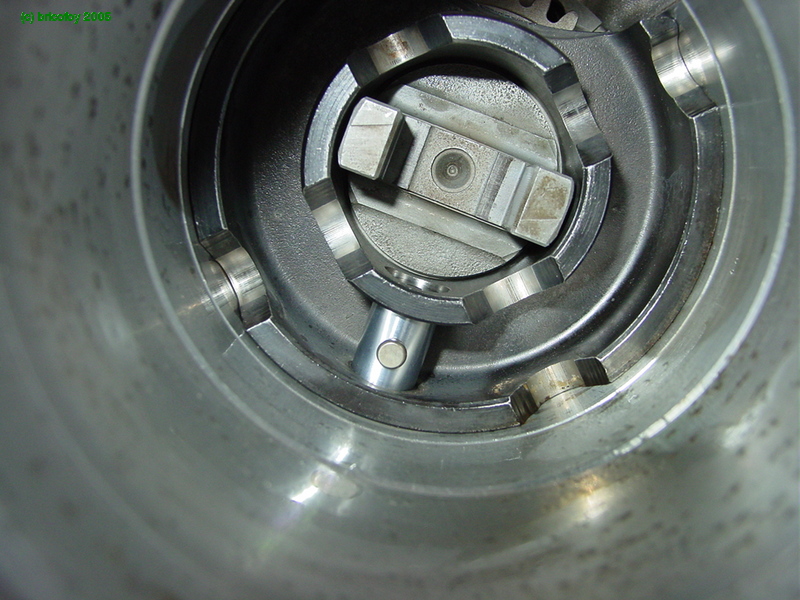
then the rotor cover :
Here it is in place with its screws :
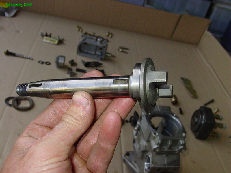
We'll now put the main shaft in place as shown below:
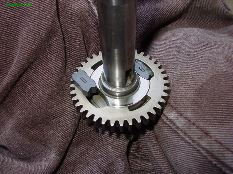
Before putting it back in its place, you have to first put in the governor drive gear along with two new elastic shims/couplers:
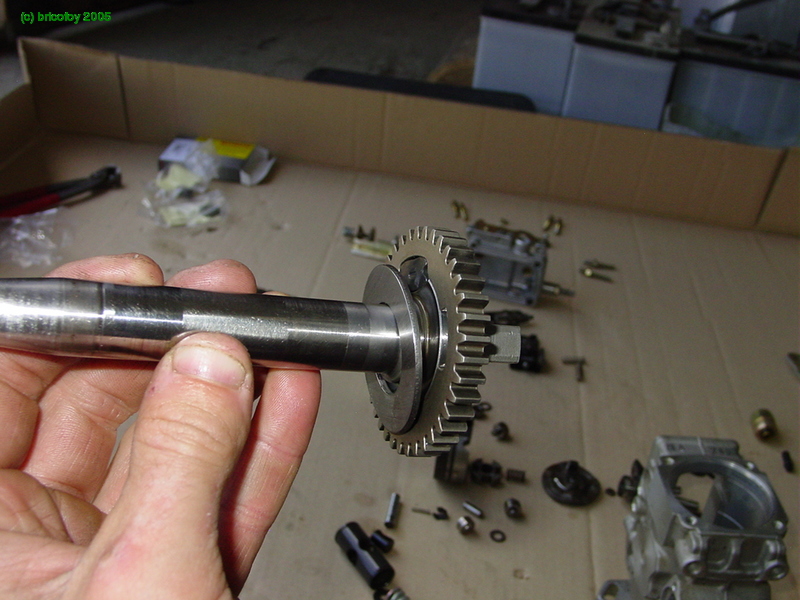
Next, add the washer that goes behind it:
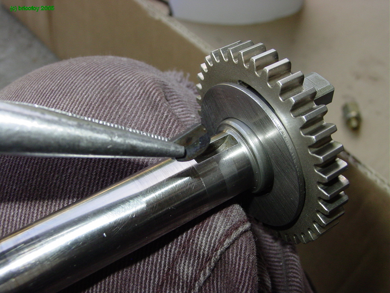
and finally the transfer pump drive key in the shaft:
Then you put the whole thing in the body of the pump:
And...here it is in its place :
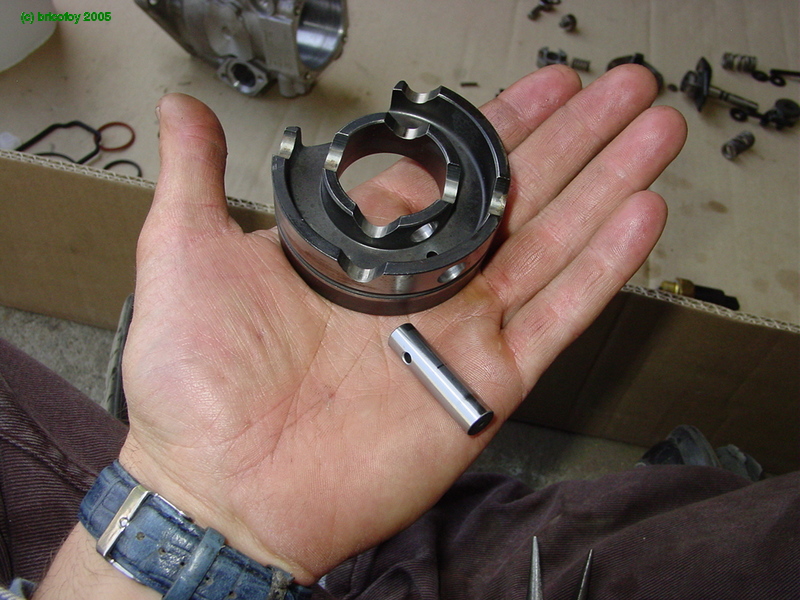
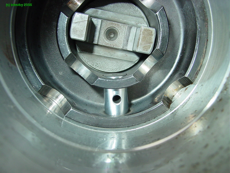
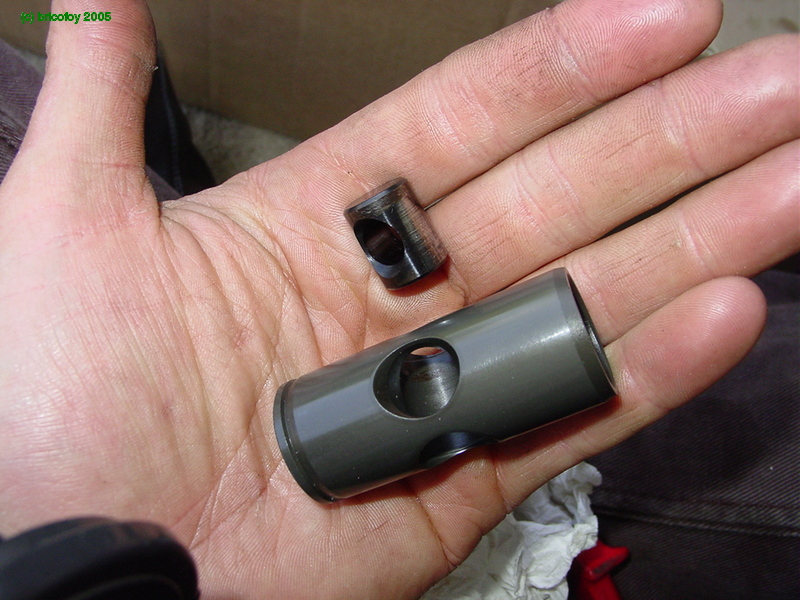
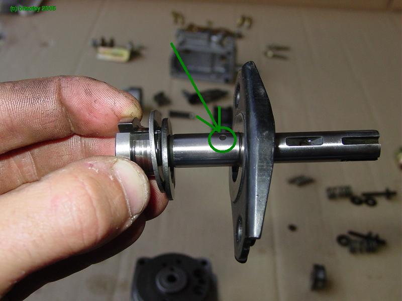
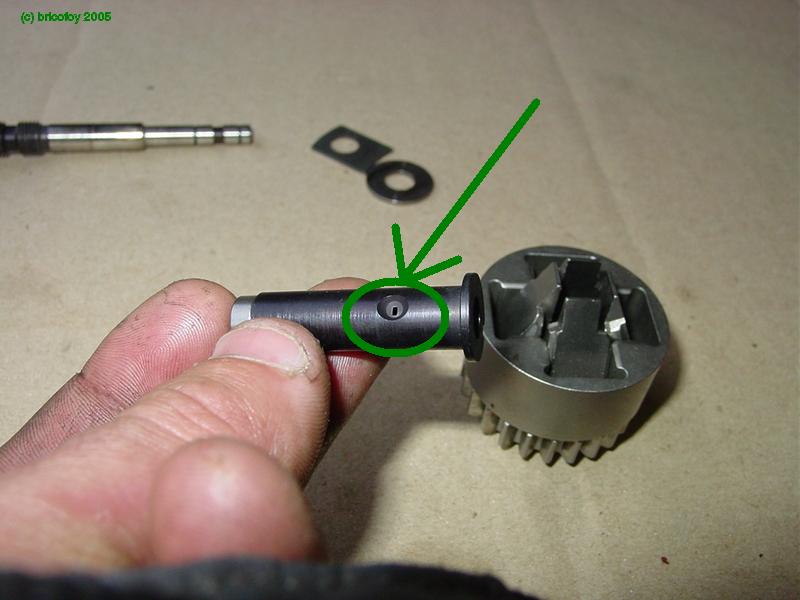
We'll now put the put the following pieces together: the roller carrier with its actuator pin for timing advance:
Put the actuator pin into the carrier (be sure to put the hole in the pin on the correct side!)
Next, put the assembly in the pump :
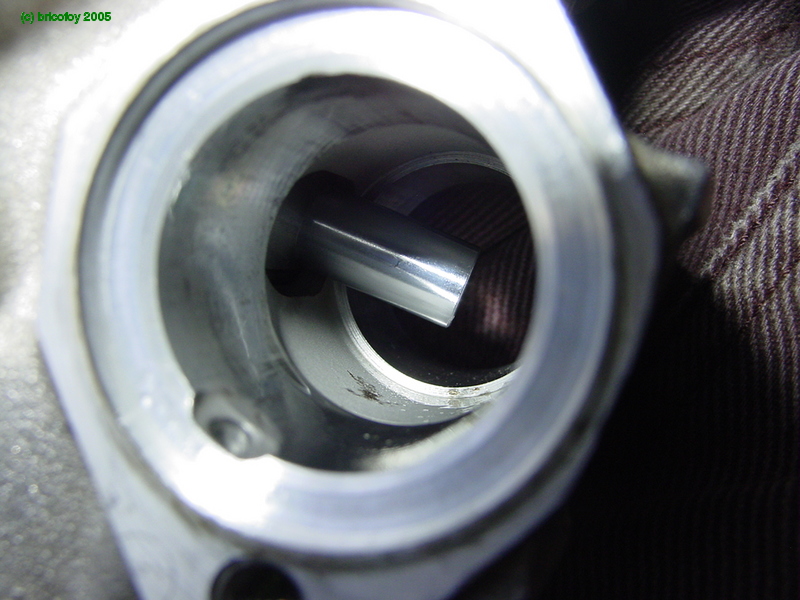
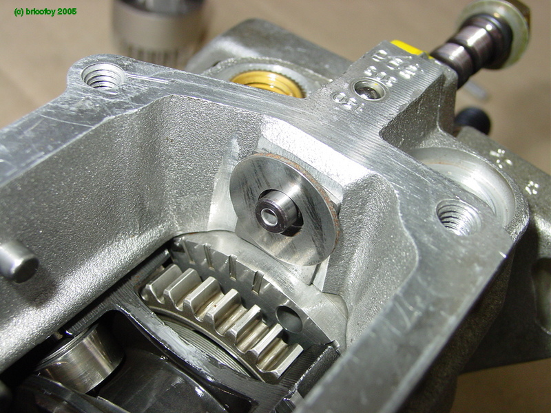
...and here's the actuator pin when it's in its appropriate place.
It sticks out into the advance mechanism's bore:
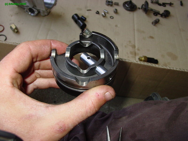
Ok, now all we have to do is assemble the roller carrier so we can put the advance piston in place like so:
Put the assembly back together :
The piston in place :
Pay close attention to the piston's orientation. The machined part of the piston that accepts the spring is installed on the side of the evacuation hole that goes to the transfer pump:
All that's left is to drop the acutator pin in place
and secure it with its pin.
Install the clip on the end of the pin:
Next, we'll put on the transfer assembly cover with a new seal:
Then, on the other side, the spring and the automatic advance mechanism (cold start advance lever / cover for us VW guys?):
Eventually, I removed the electric adavance mechanism since the 205 doesn't have this feature. I put a normal cover in its place.
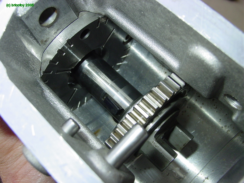
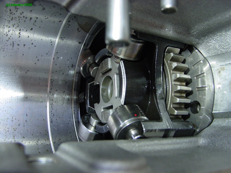
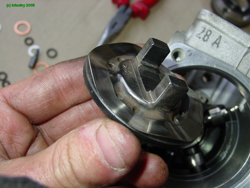
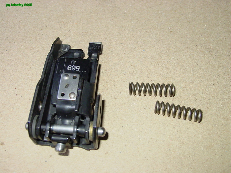
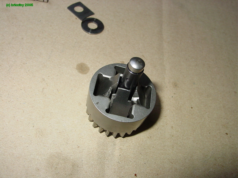
Next, you install the cross-shaped piece that drives the rest of the pump:
Then install the rollers... They are shown here on their support outside of the pump. Pay close attention to the orientation of the washer which is curved to adapt to the outside shape of the support:
Install the spring that goes in the center :
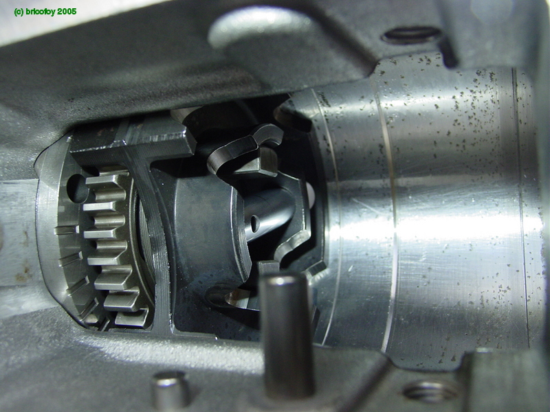
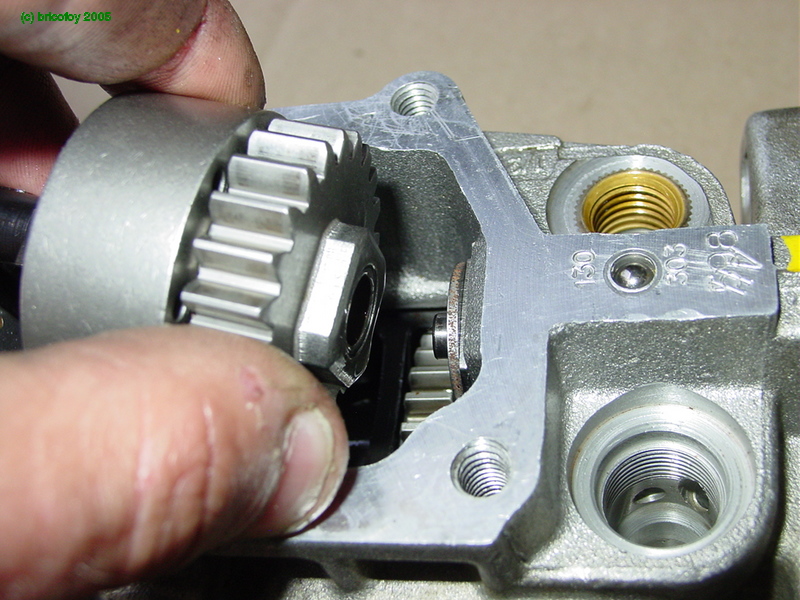
Next add the camplate which goes on top:
To align this part, the drive pin for the piston (marked in green) must be aligned with the key in the pump's shaft.
It's the cams (humps) of this plate that cause the piston's movement when the rollers pass over them. The piston moves, compresses the fuel and injection occurs. You can modify the advance by turning the roller carrier in relation to the timing advance piston's position underneath.
With this pump, I changed the camplate because this pump's original camplate didn't have the same profile. The one that's in there now comes from a 205 pump.
Now let's go on to the distributor piston:
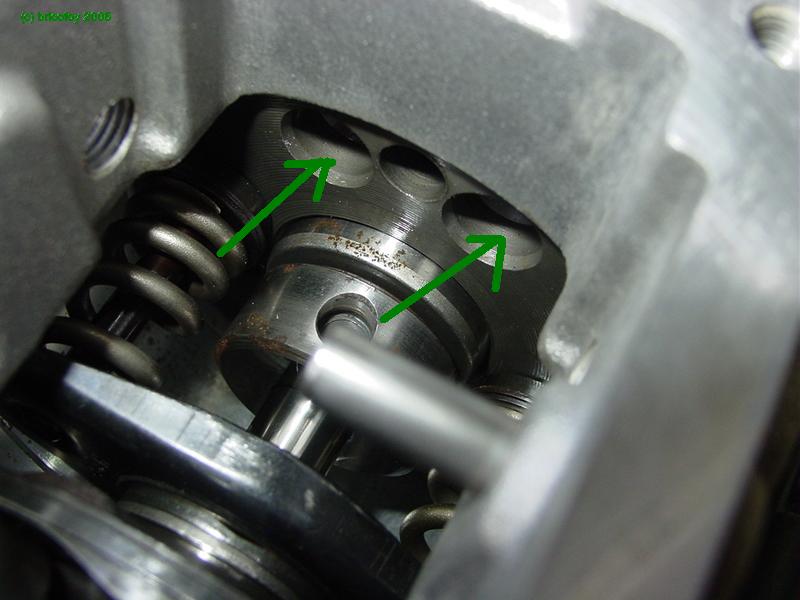
Next we add the governor assembly:
This piece, directly actuated by the governor, is going to more or less cover the piston's outlet hole (marked in green on the preceeding photo).
During injection, the piston is pushed in, pushed by the camplate. Depending on the position of the governor assembly, the hole becomes more or less blocked by the piston's movement after its stroke. This is how the amount of fuel to be injected is regulated. (when the hole is "free" the pressure is relieved through there and injection stops).
The piston is called the "distributor" because it is driven in rotation and directs the fuel towards each outlet port (pressure valve toward the injector) through each of the different holes on it.
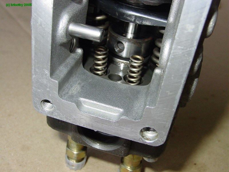
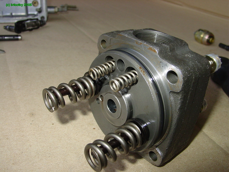
Next, we put the distributor piston back into the hydraulic head:
..and the return springs:
The spacer shim at the end of the piston:
..and it all goes into place in the pump :
We'll now reattach the governor levers and the return springs on them:
The most complicated part of this operation is the correct positioning of the springs:
l
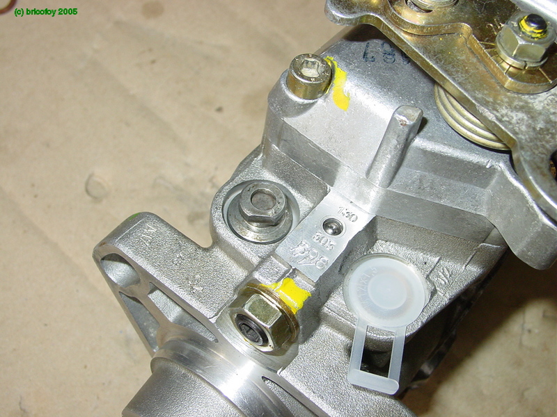
Detail of the how the special triangular head bolts (for which I made a special socket by grinding an old 13mm socket) will fit into the lever assembly:
Installation of the bolts with new aluminum gasket:
The only thing remaining on this step is to put the lever assembly in from the top:
...And no...that doesn't work. We're screwed. Impossible to do it this way. We'll have to disassemble the head and then put the levers in place before all of the rest.
By the way, on the distributor piston, you'll see the outlet orifice (marked in green), the orifice leading to the injectors (red) and the 4 grooves that fill the chamber at the end (green). The piston is hollow to allow flow through to all of that.
The head assembled with all its return springs:
The only thing left here is to put everything back into place then disassemble it one or two more times after the springs fall out in the process...and here you go:
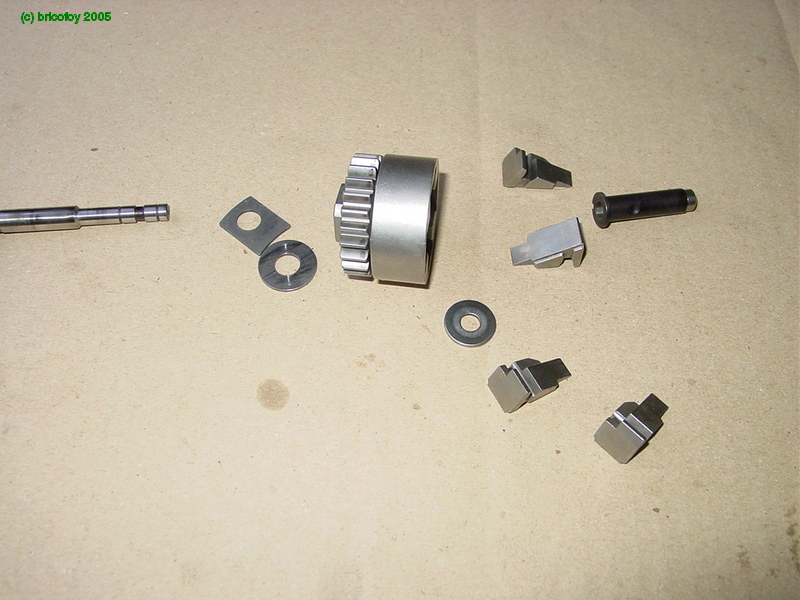
Let's go on now to the reassembly of the centrifugal governor. Here are all the pieces:
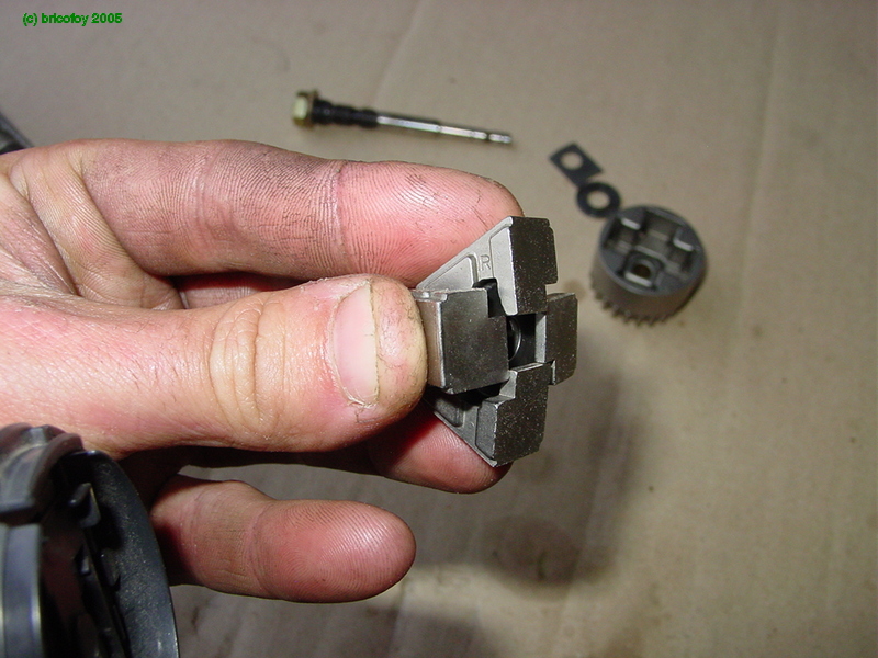
First you put together the counterweights:
Then you put them back into the body of the governor:
Next, you replace the governor lever seen below. (notice the calibrated hole that's part of the system that alters the initial fuel injection in function of the load):
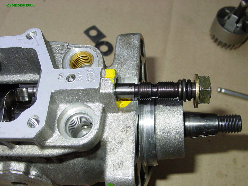
After this, you put in the governor shaft in the body of the pump:
These are the washers that go behind the governor's rotor:
the governor itself :
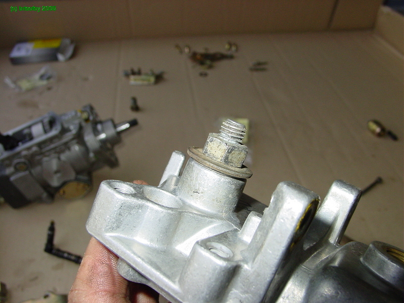
Then install the shaft and tighten it with the help of a hex key and a normal box wrench to hold the shaft in position so it doesn't move while the lock nut is tightened.
The position of this shaft is important because it regulates the system of initial injection by vacuum (?). It's wise therefore, to mark the position of this shaft during pump disassembly.
There you go... Now the pump body is complete. The only things missing are the pump cover and the transfer pressure regulation valve that I could have put on right after this, but didn't...
We'll start by removing the old lever guide sleeve:
Then we put the new sleeve in its place:
Gently push the sleeve home by using a bolt and some large washers:
Next, put in the governor shaft and return spring "capsule":
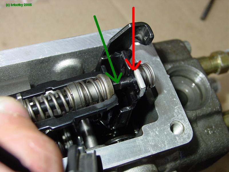
Detail shot of the attachment of the governor spring assembly on the governor lever: the flat (green) fits into the slot/grove in the lever (red) then gets pulled into place from behind:
And there you go... just have to replace the cover (with a new seal) and screw it into place.
Next, you put the throttle lever back in its place thanks to the markings on the shaft and on the lever (we would have obviously have taken care to mark it's exact position during disassembly):
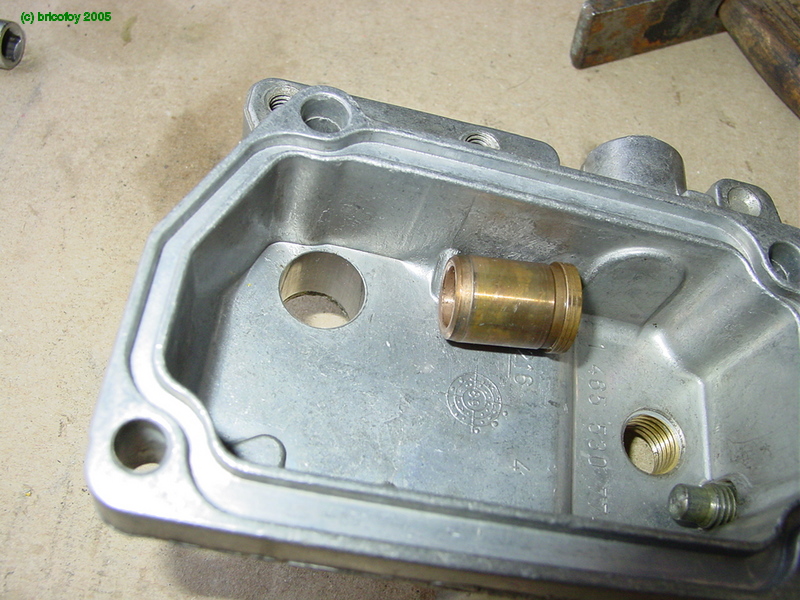
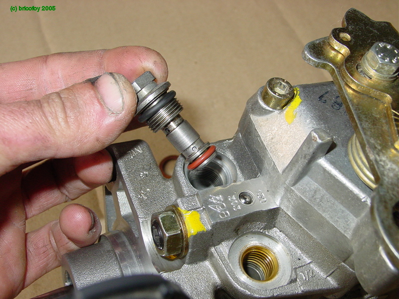
Now, put the transfer pressure regulation valve back on (with new o-ring seals, of course):
Next, add the electric fuel cutoff solenoid :
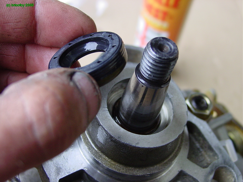
And finally, install the seal on the mainshaft (you can do this by using a large socket and the pump's shaft pulley nut to press it into place on the shaft...sorry, no photo,).
And there you go, all done. Nothing left to do but to install it onto the 205!


Whew...[/quote]
-
vaughanatworld
- Glow Plug
- Posts: 3
- Joined: Fri Jun 08, 2007 12:10 pm
Thank you.
I have more questions on this pump.
1) Where might I get calibration specifications for this pump?
( tables for timing, pressures etc. I do have the Bosch Diesel Distributor Fuel-Injection Pumps tech instruction manual)
2) Has anyone home brewed a VE pump test/calibration stand on something like an engine lathe?
3) Has anyone home brewed an injector test stand from something like a grease gun or a bottle jack?
4) To build a testor, where might I get an adapter to go from a NPT to the Compression nipple (DIN 73365) used on the VE pump and injectors.
5) Might some one know where to get a copy of DIN73365? Web or library. It is about 40 euros to buy it new. A little steep for something I only want to read once.
Thanks
Brian
-
vaughanatworld
- Glow Plug
- Posts: 3
- Joined: Fri Jun 08, 2007 12:10 pm
The program is called ESI Tronic. They pop up frequently on German eBay. The trick is finding a seller who will accept PayPal and ship to the US. I don't know of anywhere else that the software is available.
It seems like quite a few old threads have been wiped from the dieselparts server. Quite a shame. Anyway here's a similar one on the GTD forum:
http://vwdiesel.net/phpBB/viewtopic.php ... tor+tester
Andrew
It seems like quite a few old threads have been wiped from the dieselparts server. Quite a shame. Anyway here's a similar one on the GTD forum:
http://vwdiesel.net/phpBB/viewtopic.php ... tor+tester
Andrew
libbybapa,
Thank you very much for this pictorial, as it gave me the confidence to dive into a reseal of my Bosch VE pump without fear. As stated I am replacing all the seals in my pump, and I am a little confused about the important marking of governor shaft location before dis-assembly. I just got the top cover back on last night, and I was looking at this post, and realized that the governor shaft has an o-ring on it. I don't want to get it all together and then have this shaft start leaking, so I'm looking at replacing the governor shaft o-ring since the pump is out. However, I do not understand how you "mark the position of this shaft during disassembly" Is it how far the shaft gets screwed into the pump?
Thanks in advance.
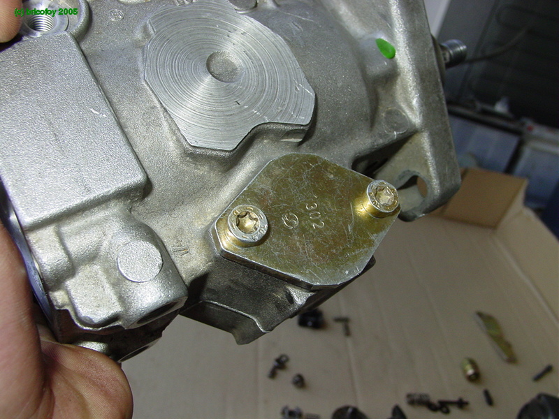
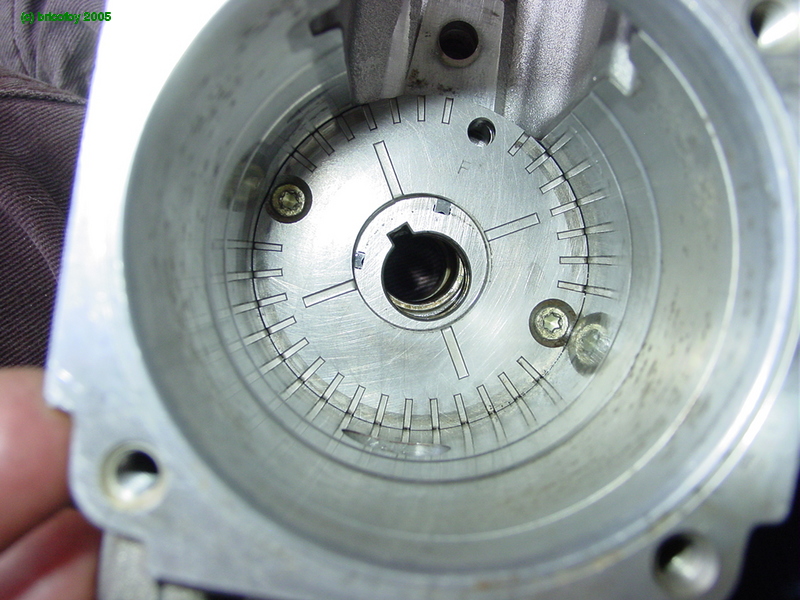
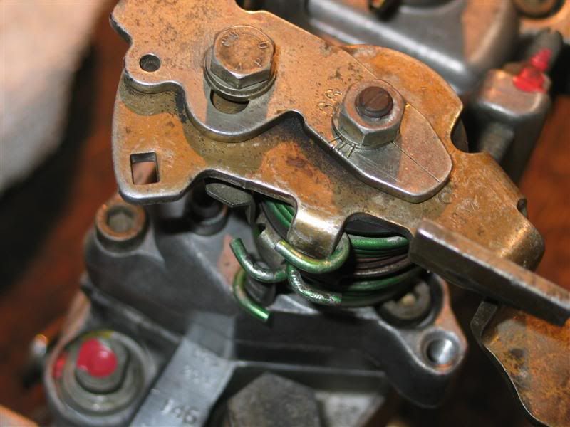
It's not the vertical level of the shaft that requires marking/resetting to previous position; it's the rotational orientation of the internal governor parts with the external governor parts. The lever that screws down on the top of the shaft meshes with the splines of the shaft; get it wrong and you will either not be able to return to low rpms for idle, or you won't be able to get enough fuel for high rpms. There's a scored line in the top of the shaft, and usually there are some scored lines in the lever that screws down on it; it's the alignment of those scored lines that you need to pay attention to. A digital photo before dissassembly is helpful; your pump could be different, but here's one of mine:
81 Pickup 1.6NA; '86 Cabriolet with 1.6 TD
I apologize, I meant the centrifugal governor shaft. It screws into the pump horizontally and from the main shaft side. I looked at it last night, and the lock nut is different than the one shown in the pictures. It is not a normal nut it seems to be like a thick washer with two squares taken out of the top to fit a holding tool into. I don't think I'm going to mess with it.
Thanks for the reply tawney, I was forewarned about the governor lever position by the great folks on this site, and got it taken care of.
Thanks for the reply tawney, I was forewarned about the governor lever position by the great folks on this site, and got it taken care of.
-
Fatmobile
- Global Moderator
- Posts: 7564
- Joined: Wed Oct 30, 2002 10:28 pm
- Location: north central Iowa
The governor shaft lock nut is usually reverse threads.
I ran into one that wasn't, it had a normal, hex lock nut.
Tp remove it; I grind down a proper sized socket until it only has 2 prongs left.
I ran into one that wasn't, it had a normal, hex lock nut.
Tp remove it; I grind down a proper sized socket until it only has 2 prongs left.
'91 Golf gasser converted to a 12mm pump, M-TDI.
'84 1.6TD Rabbit with a VNT-15 turbo, still setup to run on vegetable oil.
'84 GTI with 1.7TD pistons and intercooled.
2003 TDI wagon
2000 TDI Jetta.
'84 1.6TD Rabbit with a VNT-15 turbo, still setup to run on vegetable oil.
'84 GTI with 1.7TD pistons and intercooled.
2003 TDI wagon
2000 TDI Jetta.
-
Pup Tentacle
- Cetane Booster
- Posts: 66
- Joined: Sat Feb 16, 2008 12:50 pm
- Location: Longville, MN
I do not advocate software piracy.
The fine for non-innocent copyright infringement is $250,000 and up to 25 years in prison.
Having said that.
Bosch ESI Tronic (which is updated every year) is available (illegally) on various public file sharing networks (KAD, eMule, etc.) as a dual layer DVD image (7+ Gb) sometimes RAR compressed to 5+ Gb.
Assuming one was willing to take the risk, the download would take days even with a fast internet connection (ADSL/DSL).
It is also serialized and copy protected. The hacks and cracks are typically virus/trojan infected.
If you need it, buy it.
Pup
85 Golf NA 1.6L
85 Jetta Turbo 1.6L
83 Chevy C10 NA 6.2L
88 Chevy Suburban NA 6.2L
94 Chevy K1500 Turbo 6.5L
Hatz 1B30 powered Log splitter
85 Jetta Turbo 1.6L
83 Chevy C10 NA 6.2L
88 Chevy Suburban NA 6.2L
94 Chevy K1500 Turbo 6.5L
Hatz 1B30 powered Log splitter
-
surfcam
- Turbo Charger
- Posts: 1482
- Joined: Tue Sep 28, 2004 8:43 pm
- Location: Canada Southern Alberta
- Contact:
Its not illegal in Canada yet. We pay a copy right tax on blank DVD, casettes. ipods, and hard drives. So when the law comes in people will sue to get there money back. If there are a lot of seeders it can be had 16 hours.
99 TDI Jetta (Z1 engine code)
94 Grand Caravan
89 Dodge Gold Stream B class
http://www.antiquedollhouseofpatterns.ca/
94 Grand Caravan
89 Dodge Gold Stream B class
http://www.antiquedollhouseofpatterns.ca/
-
crossy2425
- Glow Plug
- Posts: 1
- Joined: Fri May 30, 2008 12:20 pm
-
hippiehulahooper
- Turbo Charger
- Posts: 344
- Joined: Wed Nov 02, 2005 10:47 am
- Location: kentucky
taken apart..how to clean
I have the pump from my 90 taken apart following this thread.
it says, "It goes without saying that once the pump is apart, all the pieces must be rigourously cleaned. In addition, it also greatly helps reassembly to lubricate all parts that adjust, rub or slide together with penetrating oil."
for the penetrating oil I can use WD40?
but what do I rigourously clean it with, and how?
at first I sprayed the IP with carb & choke cleaner and brushed with a brass brush. it did ok then I took it to the car wash and sprayed it with the carb & choke cleaner and then hit it with the high power sprayer. that cleaned it a lot better.
but now that it is all apart I want to make sure I get it as clean as possible for the rebuild.
90 Jetta chasis, NA mech. PS, AC.
parts needed:drivers side rain gutter, drivers side rocker panel and rear flare
86 Jetta TD(bottom end needs rebuild)
parts needed:drivers side rain gutter, drivers side rocker panel and rear flare
86 Jetta TD(bottom end needs rebuild)