Page 4 of 6
tools
Posted: Fri Apr 13, 2007 10:20 pm
by Fatmobile
I'd like to see this thread stay on course and to the point.
So to keep discussion down. How about we don't post questions.
Facts mam, just the facts.
Discussion of a tool can be posted on another thread and linked to.
... and keep the subject on home-made tools.
Posted: Sat May 12, 2007 3:04 am
by stueveone
Exhaust clamp tool. Previously mentioned bolt trick (see below for detail)
Bolt size 3 1/2 inches.
on a vise, pry apart the c-clamp. I put the clamp with the open part facing up and locked the vice on one of the sides, using a flat piece of steal wedged across the top surface of the vise to make sure it doesn't walk out. Then, with a big ass screw driver, pry via the opposite hole down and insert the bolt. I place it close to the edge, so that way, after it's in place, you can smack it with a hammer and dislodge it easily.
clamp
Posted: Sat May 12, 2007 11:20 am
by vixentd
I almost understand. except with the flat piece of steel. I have seen two people used by putting in the vise with the open end up and one person using two large rods to pry apart the clamp and then slide the bolt it, but not clear how the flat bar works. Any further explanation or a pic would be great.
Those clamps are a pain!
Priming the engine with oil
Posted: Tue Aug 21, 2007 10:14 pm
by jason
I have found that a 13mm 6 point deep well socket connected to a 3/8 in drill with a socket to drill adapter will turn the oil pump on a 1.6 and get oil flowing when placed over the shaft that normally has the vacuum pump on it (good for when your engine has sat a long time and is dry).
Jason
IP head O ring tool
Posted: Sun Nov 25, 2007 2:41 pm
by tawney
There have been several threads on this forum discussing a procedure described and refined by Libbybapa for the replacement of the O ring on the head of the Bosch injection pump. I've used the procedure; it worked really well, and saved a lot of time and trouble. For a description of that process go to page 2 of this thread:
viewtopic.php?t=5311&postdays=0&postorder=asc&start=0
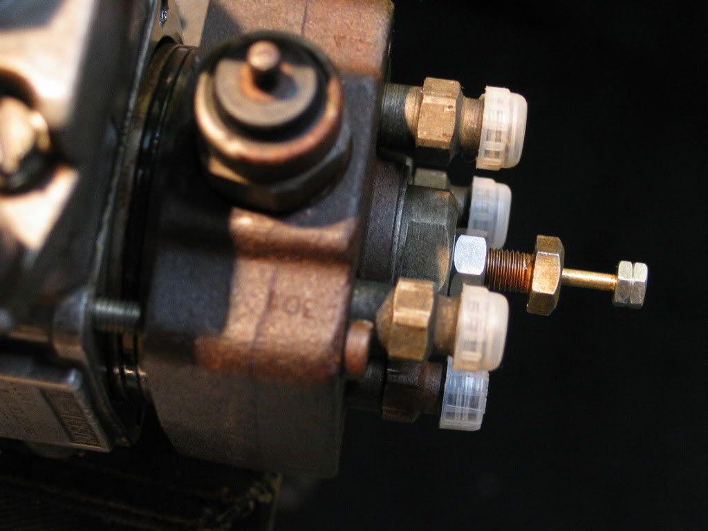
What I have wanted since my first experiment with the technique was a spring loaded center bolt that would eliminate the need for a careful balancing of the center bolt movement with the outward/inward movement of the pump head. So, here it is; I'm not a machinist, and it's a bit crude, but I've tried it already and it seemed to work fine.
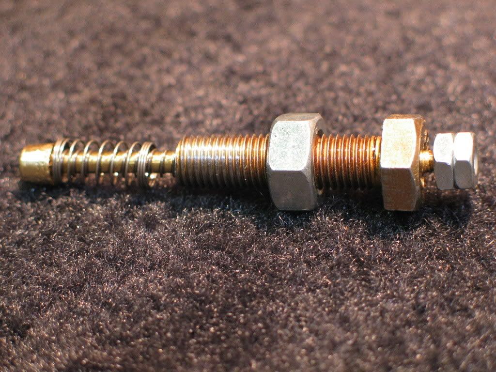
It's a 8 x 1mm bolt 3cm long drilled through the center with a 5/32" drill. Through the hole is a piece of 1/8" brass rod with a brass tip threaded on the end and two thin springs between the bolt and the tip which allow about 13mm of movement. The opposite end of the brass rod that goes through the head of the bolt is capped with two #6x32 nuts. Make sure the pump rollers are on the flat part of the cam and when you thread the bolt into the head you can see the point at which contact is made between the brass tip and the end of the injection plunger; continue threading until you've got about 10mm of movement, (before the springs bottom out,) then lock it in place with the 8mm nut on the bolt, (hand tight is good enough.) Then follow the procedure without worrying about rotating the center bolt. You can see the 2 lock nuts on the end of the brass rod move forward then back out as the head separates from the pump body and then re-seats itself when you screw it back down.
Posted: Sun Nov 25, 2007 2:48 pm
by libbybapa
Very nice. Very, very nice. When do they go on sale and how much?
Andrew
Posted: Sun Nov 25, 2007 3:08 pm
by Vincent Waldon
What Andrew said.
What I really like about the design (and which my back-of-the-napkin plan didn't provide) is that you can visually watch the plunger holder do its job... if for whatever reason something happened or you were going to run out of travel you would see it before it was too late.
AND... I suspect that mild spring/brass combination is much easier on the end of the plunger than snugging up a steel bolt repeatedly.
Great design... great choice of materials... package it with an o-ring and a HOW-TO DVD and you'll be a millionaire.... just remember us little people when you're rich and famous, eh ??

Vince
Posted: Tue Nov 27, 2007 12:42 am
by tylernt
Genius. I love it when the community comes up with stuff that the VW engineers, Bentley authors, and Robert Bosch himself never dreamed of.
To stay on topic, here's my timing belt tensioner. I got some snap ring pliers but sadly, they don't open up big enough. So I have two allen keys just barely small enough to fit into the two tensioner holes. The long part of the first one goes in the front hole, the short part goes into the rear hole and the long part hangs down. Then you rotate it up until it hits the front allen key, and stick the end into your smallest socket (4.5mm is what I have, it's too big, but it works) on a really long extension (a foot or more). Now you bend the rear allen key against the front allen key, using the extension for leverage, and this tightens the belt. The nice thing is, you'll not be tempted to put too much tension on the belt because your allen key will start to bend first.
Dial indicator adapter
Posted: Wed Nov 28, 2007 8:13 pm
by tawney
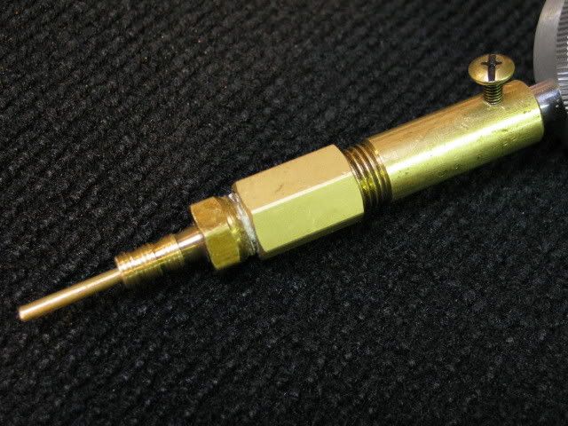
Take a 1/4" brass pipe nipple, (cut the threaded part off of one end if you want,) drill one end of it out to 3/8"; (don't ask me why 1/4" pipe is almost 3/8" on the inside!) it will then fit snuggly over the large, non-moving part of the dial indicator stem. (You can drill and tap a set screw in the side if you want.) Screw a 1/4" coupling onto the other end of the nipple, then screw a brass 1/4" barbed pneumatic hose fitting onto that. (Most pneumatic fittings are 3/8" on the barbed side; it must be 1/4".) Cut threads over the barbed end with a 8mm X 1 die. Then cut the barbed fitting a little shorter so that it is about the same length as the bolt from the end of the pump. If you make the adapter shorter or longer than the stem that came on the gauge, buy a piece of 1/8" brass rod; cut it to the length you need, thread one end with a #4-40 die. Now it will screw into the end of the dial indicator after you remove the tip that it came with. I'm not certain that all dial indicator tips are threaded for #4-40, but that size works on all three gauges I have.
One difficulty I had was that when I installed the adapter on the dial indicator, the tip was enough off-center to interfere with the free movement of the rod. My solution was to take the 3/8 drill bit again and ream out the hole in the 1/4" brass pipe a little bit, then install the set screw on the side that will push the hole toward center when you tighten it down on the gauge. You can make a really long adapter if you want.
Posted: Thu Nov 29, 2007 11:55 pm
by CoolAirVw
Tawney. Its neat that you made one and its functional. I had a similar idea to make mine. Here's mine.
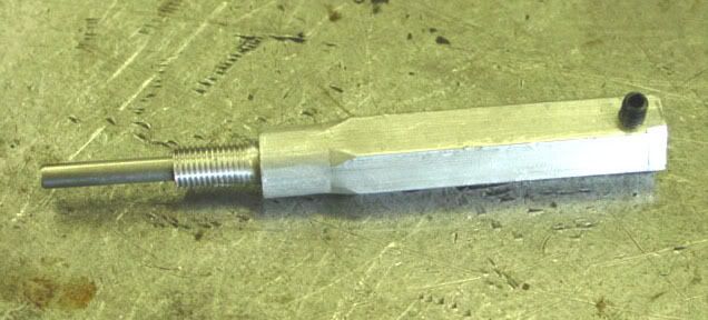
It works great, looks good and slides smoothly, but its a little too long. Since my car is a turbo, the turbo oil line makes it a little hard to install. It would be great on a NA engine.
Maybe I'll cut it shorter or sell it on the classifieds and make a shorter one.
Transaxle Dipstick
Posted: Sun Jan 13, 2008 3:08 am
by wbhgrace
Dipstick for checking transaxle oil level through the speedometer cable hole.
http://www.flickr.com/photos/13558423@N02/2170694143/
I came up with the correct oil depth for my '81 Rabbit's FF 5 speed by draining and refilling with the correct amount of oil (2 quarts + 4 fl oz for the FF). After refilling, the oil level was 1.8 inches below the surface of the trans casting at the speedometer cable hole. This was measured perpendicular to the casting surface at the approximate center of the hole (with the car level). Other transaxle models may have different "full" oil depths so I'd recommend doing a drain and refill to calibrate this tool for your car.
Posted: Fri Feb 08, 2008 1:41 pm
by Brian Rages
Not a homemade tool, but probably a free one:
One of the offset oxygen sensor wrenches (you can freely borrow O2 wrench sets from many auto parts stores) is just the right size to loosen the nut on the A2 strut towers. By using the offset wrench, you can hold the strut shaft from moving while you loosen the nut.
exhaust system C clamp
Posted: Mon Feb 11, 2008 6:25 pm
by One W/the truckers
I was having trouble installing the 2nd C clamp on my 86 Golf diesel. So I went in and had lunch and came up with this idea that worked very well. I put the passenger side C clamp on first, then put a 2X4 across the fenders, put the C clamp on the exhaust pipe flange, tied a piece of rope around the top of the c clamp and around the 2X4, used a screwdriver to make a tournequet out of the rope to pull the clamp apart, moved the clamp over to the exhaust manifold, released the tournequet and it only took a couple of minutes.
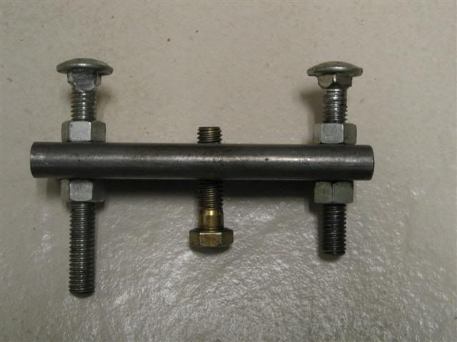
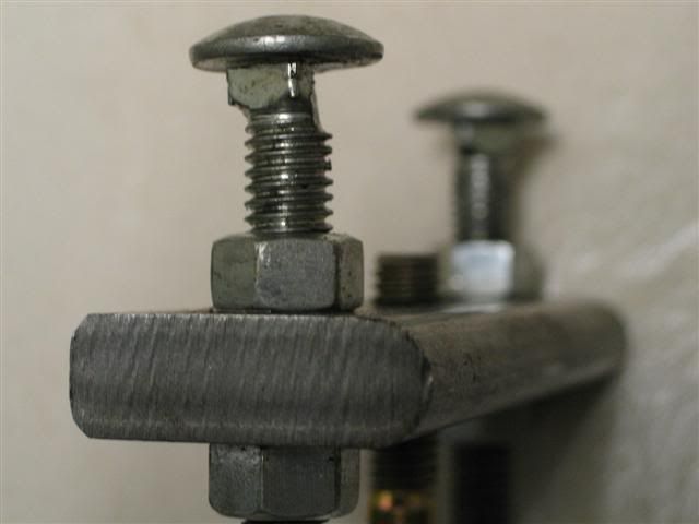
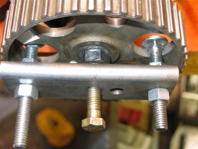
IP sprocket remover
Posted: Fri Mar 14, 2008 5:20 pm
by tawney
Re: Dial indicator adapter
Posted: Fri Mar 14, 2008 7:47 pm
by Quantum-man
tawney wrote:Take a 1/4" brass pipe nipple, (cut the threaded part off of one end if you want,) drill one end of it out to 3/8"; (don't ask me why 1/4" pipe is almost 3/8" on the inside!) it will then fit snuggly over the large, non-moving part of the dial indicator stem. (You can drill and tap a set screw in the side if you want.) Screw a 1/4" coupling onto the other end of the nipple, then screw a brass 1/4" barbed pneumatic hose fitting onto that. (Most pneumatic fittings are 3/8" on the barbed side; it must be 1/4".) Cut threads over the barbed end with a 8mm X 1 die. Then cut the barbed fitting a little shorter so that it is about the same length as the bolt from the end of the pump. If you make the adapter shorter or longer than the stem that came on the gauge, buy a piece of 1/8" brass rod; cut it to the length you need, thread one end with a #4-40 die. Now it will screw into the end of the dial indicator after you remove the tip that it came with. I'm not certain that all dial indicator tips are threaded for #4-40, but that size works on all three gauges I have.
One difficulty I had was that when I installed the adapter on the dial indicator, the tip was enough off-center to interfere with the free movement of the rod. My solution was to take the 3/8 drill bit again and ream out the hole in the 1/4" brass pipe a little bit, then install the set screw on the side that will push the hole toward center when you tighten it down on the gauge. You can make a really long adapter if you want.
Nice use of brass... How about an 8mm brass bolt with nut long enough reach end of piston. Scratch one mark on a flat of bolt head. Screw bolt in until bolt touches piston. Note orientation of scratchmark. Back off 1 turn and gently turn engine with wrench to reach bolt again. I'd call that 1mm timing How about using Tawney's simple sprung item only incorporate a door jamb light switch to make or break a LED circuit?
Each 0.05mm change is 18deg on the screw. so 0.88 is approximately 45 degree turn. 0.94 is approx 22.5 deg.
Alternately each flat on bolt is 60deg or 0.167mm; so half flat is 30deg or 0.08mm